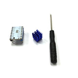
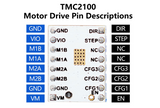
These stepper drivers are built around the TMC2100 stepper driver IC. TMC2100 drivers have a number of advantages, the most notable of which is their quiet operation due to the stealthChop technology.
These drivers are made in the Pololu-style 'stepstick' footprint. They are compatible with any control board that accepts this footprint, including RAMPS and RUMBA+. They come with the headers already soldered in place, and also come complete with a heatsink, with adhesive already attached. Perfect!
Unlike many other stepstick designs, the TMC2100 stepstick has the TMC2100 IC and all components sit on the bottom of the stepstick - so the top is a flat surface for the heatsink to attach to. This maximizes the thermal dissipation of the design when a heatsink is attached.
We put each and every one of these stepper drivers through a full functional test and have pre-set the current in the region of 500-600mA.
Specifications:
- Operating Voltage Range: 5.5-46V
- Logic Voltage Range: 3-5.2V
- Continuous Current per Phase: 1.2A
- Maximum Current per Phase: 2A
- Microstep Resolutions: 1, 1/2, 1/4, 1/8, 1/16, 1/32
Configuration:
MICROSTEPPING MODE:
The TMC2100 modules can operate in a number of different microstepping modes, from 1 to 1/16th microstepping, with some modes including interpolation up to 1/256th microstepping.
The TMC2100 configuration pins do not behave in exactly the same way as the microstepping select pins on A4988 and DRV8825 drivers. The TMC2100 configuration pins can be put into three different states - pulled high, pulled low, or left floating. Many common control boards (including RUMBA+ and RAMPS) have pullup or pulldown resistors on some of the configuration pins that prevent using certain modes of the TMC2100. To prevent this from being a problem, the configuration pins on these stepper drivers have not been connected to the pins on the header, and can only be changed by soldering the jumpers on the board as shown below. The default configuration these drivers ship in is with CFG1, CFG2 and CFG3 open - which results in stealthChop mode running at 1/16th microstepping with interpolation to 1/256th, with the motor current set by the onboard potentiometer. This is the mode we recommend for most applications - refer to the below table for other modes available.
| CFG2 | CFG1 | Steps | Interpolation | Mode |
| GND | GND | 1 | - | Spread Cycle |
| GND | VIO | 1/2 | - | Spread Cycle |
| GND | OPEN | 1/2 | 1/256 | Spread Cycle |
| VIO | GND | 1/4 | - | Spread Cycle |
| VIO | VIO | 1/16 | - | Spread Cycle |
| VIO | OPEN | 1/4 | 1/256 | Spread Cycle |
| OPEN | GND | 1/16 | 1/256 | Spread Cycle |
| OPEN | VIO | 1/4 | 1/256 | Stealth Chop |
| OPEN | OPEN | 1/16 | 1/256 | Stealth Chop |


