This item is archived from our catalog and no longer for sale. This page is available as a reference only.
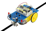
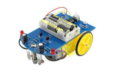
D2-1 Intelligent Tracking Car
The first step: Part of the circuit welding
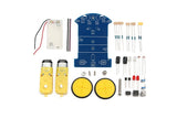
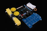
This part is relatively simple, according to the principle of welding the original height from low to high as the welding sequence. First we should solder eight resistors, do not forget to use a multimeter to confirm their resistance. Some other polar components, such as triode, led lights, electrolytic capacitors, etc.. These components need to refer to our picture to the direction of welding, welding capacitors, the short pin is negative. When welding the LED, the long pin is positive. Note that the welding time can not be too long, which may burn the components, D4, D5, R13, R14 can be temporarily not welded, integrated circuit chip can also be temporarily not inserted into the base.
Step 2: Mechanical assembly
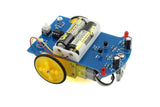
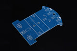
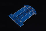
First of all we need to use screws and nuts to fix the caster on the PCB board, and then paste the battery box on the PCB board through the double-sided adhesive, the battery box on the wire through the reserved hole and then welded to the PCB board, red line connect to the + 3V power supply, yellow line link to grounding, then we need to assemble the wheels, first connected the fixed hole to the paddle of the motor, and then fixed with a screw to prevent the wheels off, finally need to have two wheels with motor to affixed to a fixed position on the PCB board. Finally, the wire of the motor is also welded to the fixed position on the pcb board.
Step 3: Install the photoelectric circuit
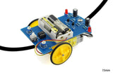
Install the photoresistor and the light-emitting diode on the opposite side of the pcb, that is, at the bottom of the car's front, keep the ground distance of about 5mm, and keep the resistance and the distance between the diodes is about 5mm, and finally the power test.
Step4: Car debugging
Plug the two AA batteries into the battery box, and then turn the switch to the "on" position, the car should be kept moving forward, this time if you hold the left of the photosensitive resistor, the car on the right side of the wheel should turn, if you hold the right of the resistor, the left side of the wheel should be rotated, if the car has been running back, then as long as exchange of the wire of two motor at the same time, if only one side of the back, then only need to exchange the the wire of back side.
Package list
|
Components |
Specification |
Quantity |
|
Voltage Comparator |
LM393 |
1 |
|
IC Socket |
8-pin |
1 |
|
Electrolytic Capacitor |
100uF |
2 |
|
Adjustable Resistor |
10K |
2 |
|
Color Ring Resistor |
3.3K ohm |
2 |
|
Color Ring Resistor |
51 ohm |
4 |
|
Color Ring Resistor |
1K ohm |
2 |
|
Color Ring Resistor |
10 ohm |
2 |
|
Photoresistor |
CDS5 |
2 |
|
LED |
3mm |
2 |
|
LED |
5mm |
2 |
|
Triode |
8550 |
2 |
|
Switch |
|
1 |
|
Reduction Motor |
JD3-100 |
2 |
|
Car Wheel Piece |
|
6 |
|
Silica Gel |
25*2.5mm |
2 |
|
Car Wheel Screw |
M3x10mm |
4 |
|
Car Wheel Screw Nut |
M3 |
4 |
|
Hub Screw |
M2.2*7mm |
2 |
|
Universal Wheel Screw |
M5x30mm |
1 |
|
Universal Wheel Screw Nut |
M5 |
1 |
|
Universal Wheel |
M5 |
1 |
|
PCB |
D2-1 |
1 |
|
Connection Wire |
Red |
1 |
|
Connection Wire |
Black |
1 |
|
Battery Case |
AAx2 |
1 |


