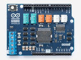
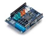
The Arduino Motor Shield is based on the L298 (datasheet), which is a dual full-bridge driver designed to drive inductive loads such as relays, solenoids, DC and stepping motors. It lets you drive two DC motors with your Arduino board, controlling the speed and direction of each one independently. You can also measure the current absorption of each motor, among other features. The shield is TinkerKit compatible, which means you can quickly create projects by plugging TinkerKit modules to the board.
This shield have two separate channels, called A and B, that each use 4 of the Arduino pins to choose the rotation direction, vary the speed, fast brake or sense the current that is flowing through the motor. In total there are 8 pins in use on this shield. You can use each channel separately to drive two DC motors or combine them to drive one bipolar stepper motor. The shield can supply 2 amperes per channel, for a total of 4 amperes maximum.
This shield has the 1.0 standard pinout that consist in 4 additional pins: 2 of them placed near the AREF pin, that are used for TWI communication, and the other 2 are placed near the RESET pin. The IOREF pin is used to adapt the shield to the board on which is mounted. The last one is not connected and is reserved for future uses.
Technical Specifications
| Operating Voltage | 5V to 12V |
| Motor controller | L298P, Drives 2 DC motors or 1 stepper motor |
| Max current | 2A per channel or 4A max (with external power supply) |
| Current sensing | 1.65V/A |
| Free running stop and brake function |
Input and Output
This shield has two separate channels, called A and B, that each use 4 of the Arduino pins to drive or sense the motor. In total there are 8 pins in use on this shield. You can use each channel separately to drive two DC motors or combine them to drive one bipolar stepper motor.
The shield's pins, divided by channel are shown in the table below:
| Function | pins per Ch. A | pins per Ch. B |
| Direction | D12 | D13 |
| PWM | D3 | D11 |
| Brake | D9 | D8 |
| Current Sensing | A0 | A1 |
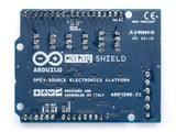
If you don't need the Brake and the Current Sensing and you also need more pins for your application you can disable this features by cutting the respective jumpers on the back side of the shield.
The additional sockets on the shield are described as follow:
- Screw terminal to connect the motors and their power supply.
- 2 TinkerKit connectors for two Analog Inputs (in white), connected to A2 and A3.
- 2 TinkerKit connectors for two Aanlog Outputs (in orange in the middle), connected to PWM outputs on pins D5 and D6.
- 2 TinkerKit connectors for the TWI interface (in white with 4 pins), one for input and the other one for output.
Documents:


