This gearmotor consists of a high-power, 6 V brushed DC motor combined with a 74.83:1 metal spur gearbox, and it has an integrated 48 CPR quadrature encoder on the motor shaft, which provides 3591.84 counts per revolution of the gearbox’s output shaft. The gearmotor is cylindrical, with a diameter just under 25 mm, and the D-shaped output shaft is 4 mm in diameter and extends 12.5 mm from the face plate of the gearbox. This gearmotor is also available without an encoder.
Key specifications:
| voltage | no-load performance | stall extrapolation |
|---|---|---|
| 6 V | 130 RPM, 550 mA | 11 kg⋅cm (150 oz⋅in), 6.5 A |
Dimensions
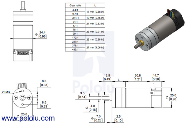
The diagram below shows the dimensions of the 25D mm line of gearmotors (units are mm over [inches]). This diagram is also available as a downloadable PDF (171k pdf).
 |
|
Dimensions of the Pololu 25D mm metal gearmotors with encoders. Units are mm over [inches]. |
|---|
Warning: Do not screw too far into the mounting holes as the screws can hit the gears. We recommend screwing no further than 6 mm (0.24″) into the screw hole.
 |
|
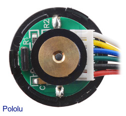
25D mm metal gearmotor with 48 CPR encoder (with end cap removed). |
|---|
 |
Using the encoder
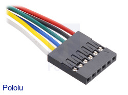
A two-channel Hall effect encoder is used to sense the rotation of a magnetic disk on a rear protrusion of the motor shaft. The quadrature encoder provides a resolution of 48 counts per revolution of the motor shaft when counting both edges of both channels. To compute the counts per revolution of the gearbox output, multiply the gear ratio by 48. The motor/encoder has six color-coded, 8″ (20 cm) leads terminated by a 1×6 female header with a 0.1″ pitch, as shown in the main product picture. This header works with standard 0.1″ male headers and our male jumper and precrimped wires. If this header is not convenient for your application, you can pull the crimped wires out of the header or cut the header off. The following table describes the wire functions:
| Color | Function |
|---|---|
| Red | motor power (connects to one motor terminal) |
| Black | motor power (connects to the other motor terminal) |
| Green | encoder GND |
| Blue | encoder Vcc (3.5 V to 20 V) |
| Yellow | encoder A output |
| White | encoder B output |
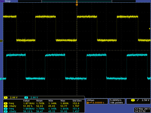
The Hall sensor requires an input voltage, Vcc, between 3.5 and 20 V and draws a maximum of 10 mA. The A and B outputs are square waves from 0 V to Vcc approximately 90° out of phase. The frequency of the transitions tells you the speed of the motor, and the order of the transitions tells you the direction. The following oscilloscope capture shows the A and B (yellow and white) encoder outputs using a motor voltage of 6 V and a Hall sensor Vcc of 5 V:
 |
|
Encoder A and B outputs for 25D mm HP 6V metal gearmotor with 48 CPR encoder (motor running at 6 V). |
|---|
By counting both the rising and falling edges of both the A and B outputs, it is possible to get 48 counts per revolution of the motor shaft. Using just a single edge of one channel results in 12 counts per revolution of the motor shaft, so the frequency of the A output in the above oscilloscope capture is 12 times the motor rotation frequency.
Dimensions
| Size: | 25D x 69L mm1 |
|---|---|
| Weight: | 103 g |
| Shaft diameter: | 4 mm |
General specifications
| Gear ratio: | 74.83:1 |
|---|---|
| No-load speed @ 6V: | 130 rpm |
| No-load current @ 6V: | 550 mA |
| Stall current @ 6V: | 6500 mA |
| Stall torque @ 6V: | 150 oz·in |
| Motor type: | 6.5A stall @ 6V (HP 6V) |
| Lead length: | 8 in2 |
| Encoders?: | Y |


