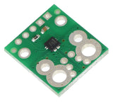
This board is a simple carrier of Allegro’s ±15.5 A ACS711 Hall effect-based linear current sensor with overcurrent fault output, which offers a low-resistance (~0.6 mΩ) current path and electrical isolation up to 100 V. This version accepts a bidirectional current input with a magnitude up to 15.5 A and outputs a proportional analog voltage centered at Vcc/2 with a typical error of ±5%. It operates from 3 V to 5.5 V, so it can interface directly to both 3.3 V and 5 V systems.
This sensor has an operating voltage of 3 V to 5.5 V and an output sensitivity of 90 mV/A when Vcc is 3.3 V (or 136 mV/A when Vcc is 5 V). The following list details some of the sensor’s key features:
- Designed for bidirectional input current from -15.5 A to 15.5 A (though the robust sensor IC can tolerate 100 ms transient current spikes up to 100 A).
- Conductive path internal resistance is typically 0.6 mΩ, and the PCB is made with 2-oz copper, so very little power is lost in the board.
- Use of a Hall effect sensor means the IC is able to electrically isolate the current path from the sensor’s electronics (for applications up to 100 V), which allows the sensor to be inserted anywhere along the current path and to be used in applications that require electrical isolation.
- 100 kHz bandwith.
- Good accuracy and reliability: factory calibration results in a typical total output error of ±5% at room temperature, the output offset voltage is extremely stable, and the sensor has zero magnetic hysteresis.
- Overcurrent FAULT output latches low when current magnitude exceeds 15.5 A.
- Operating temperature range of -40°C to 125°C.
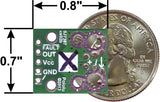
The pads are labeled on the bottom silkscreen, as shown in the picture to the right. The silkscreen also shows the direction that is interpreted as positive current flow via the +i arrow.
This 15.5 A current sensor is marked with a black X.
Using the sensor
Electrical connections
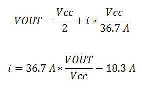
The sensor requires a supply voltage of 3 V to 5.5 V to be connected across the Vcc and GND pads, which are labeled on the bottom silkscreen. The sensor outputs an analog voltage that is linearly proportional to the input current. The quiescent output voltage is Vcc/2 and changes by 90 mV per amp of input current (when Vcc = 3.3 V), with positive current increasing the output voltage and negative current decreasing the output voltage. The relationship between the instantaneous input current, i, and sensor output voltage, VOUT, can be represented by the following equations:
 |
The FAULT pin is normally high and latches low when the current exceeds ±15.5 A. Once the


